
Proximity Sensor Wiring Diagram and Connection Procedure ETechnoG
As an example, let's reference an inductive proximity sensor. When a target (the object that a sensor is detecting) comes within sensing range of the sensor, the sensor output turns on and current flows. A 3-wire sensor typically is color coded with one brown wire, one blue wire and one black wire.
4 Wire Oxygen Sensor Wiring Diagram Cadician's Blog
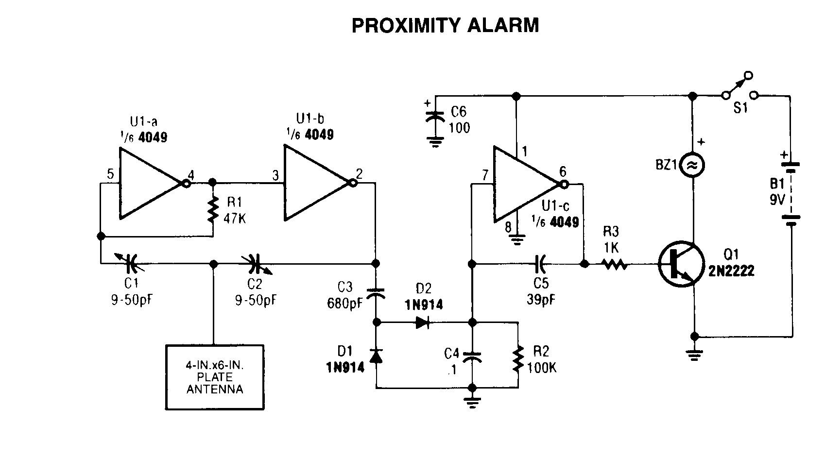
The proximity sensor circuit diagram is shown in the above figure which consists of different blocks such as oscillator block, electrical induction coil, power supply, voltage regulator, etc. Proximity Sensor Working Principle

[DIAGRAM] 6 Wire Wiring Diagram Free Download
Following the proper wiring diagram is crucial for the sensor to function correctly and provide accurate detection. Wiring a 3 Wire Proximity Sensor: Step-by-Step Guide Wiring a 3 wire proximity sensor may seem complex at first, but with this step-by-step guide, you'll be able to do it with ease. Step 1: Gather the necessary tools and materials.

Inductive Proximity Sensor Wiring Diagram Pinout
The Japanese Industrial Standards (JIS) define proximity sensors in JIS C 8201-5-2 (Low-voltage switchgear and controlgear, Part 5: Control circuit devices and switching elements, Section 2: Proximity switches), which conforms to the IEC 60947-5-2 definition of non-contact position detection switches.
Proximity Sensor Wiring Diagram Collection
A typical 3 wire proximity sensor wiring diagram consists of three wires, usually designated as Black, White, and Red. The black wire is used to provide power to the proximity sensor and the white wire is used to receive the signal from the sensor. The red wire is used to connect the proximity sensor to the control system.

2wire Proximity Sensor Wiring Diagram Wiring Diagram
Ig5953 Ifm Electronic Inductive Barrel Style Proximity Sensor Pnp Npn Output 8 Mm Detection Ip68 M18 X 1 Rs Components. If5645 Ifm Electronic M12 X 1 Inductive Proximity Sensor Barrel Pnp Npn Output 2 Mm Detection Ip67 285 706 Rs Components. Ifm Efector Im0011 Block Inductive Proximity Sensor 15 Mm Detection Range 20 To 250 Vac Dc Ip65 Allied.

2 Wire Proximity Sensor Wiring Diagram Free Wiring Diagram
2 Wire Proximity Sensor Wiring Diagrams are the diagrams used to wire up two-wire proximity sensors, which are the most common type of sensor used for industrial automation applications. This type of sensor is capable of detecting the presence of a target object within a certain range and can provide precise measurements of its position.
Inductive Proximity Sensor Wiring Diagram Pinout Wiring Diagram
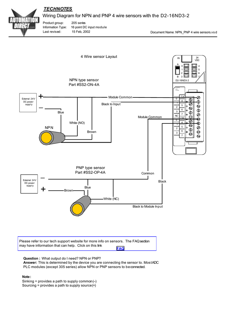
Electrical wiring of sensors What you need to know about wiring of sensors Which output type do you need: PNP or NPN?What is the difference between normally open and normally closed? We will explain it for you. PNP output (Sourcing output +24 V DC)

Wiring a Metal Detector with NPN Proximity Sensor on Arduino
A 3 wire proximity sensor wiring diagram involves connecting three wires to any type of electrical device. The specific connection of these wires will depend on the application and the type of sensor being used. Generally speaking, there are two common types of 3 wire proximity sensors: inductive and capacitive.

3 Wire Proximity Sensor Wiring Diagram Wiring Diagram
A proximity sensor is a general word for sensors that are designed to detect without contacting the detecting object and replace contact detection methods such as limit switches. It has the ability to convert the observed object's movement and presence information into electrical impulses.

Proximity Sensors Inductive and Capacitive Proximity Sensors with Arduino
A 3-wire inductive proximity sensor is an electronic device that can detect ferrous (Fe) targets without any physical contact. When it detects that target, it operates an internal electronic switch. Because the sensor is an electronic device it requires a DC power source.

Princípio de funcionamento do Sensor de Proximidade Sensor De Proximidade Indutivo / Sensor de
Sensor 1 is reading 0v which is correct. Sensor 2 and 3 read 8.33v and 25v respectively. Since sensors 2 and 3 are trigger, I would've thought those readings would've been the voltage applied across them (15v and 11v) with slightly lower values due to resistance.

21 Beautiful Proximity Sensor Wiring Diagram
Quickly access technical documents for Allen-Bradley Bulletin 875 capacitive proximity sensors and 802/871 inductive proximity sensors.. 871F 2-wire AC/DC Proximity Sensors Installation Download. 871F Proximity Sensors Installation. 871TM Inductive Proximity Sensors Division 1 Installation Wiring Diagrams Use your product..

4 Wire Proximity Sensor Wiring Wiring Draw
A 3 wire proximity sensor wiring diagram is a valuable resource for any electronics engineer. It will help you properly install, wire and test a sensor. Using a wiring diagram saves time when troubleshooting any electrical problems, as it provides the exact point of connection for each component.

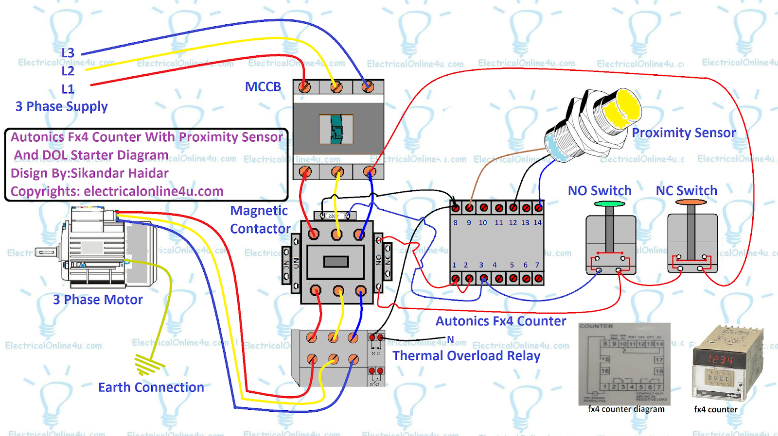
How to wiring proximity sensors with PLC Omron CP1E and create create project with CXProgrammer
By Lambda Geeks Proximity sensors are widely used in various industries and applications to detect the presence or absence of objects within a certain range. These sensors work by emitting electromagnetic fields or beams and measuring the changes in the field or beam when an object is detected.

2 Wire Proximity Sensor Wiring Diagram Free Wiring Diagram
How to wiring (NPN and PNP) 3 wire proximity sensor, and how to identify if PNP or NPN in a circuit diagram.what is a proximity sensor, how does it work a 3w.